Industry Trends · Analysis
Fire Alarm System Integration: How the Connections Work
Fire alarm system integration means the fire alarm control panel talks to other building systems. It either monitors or controls them, or it shares wiring and network infrastructure with them. Some connections are essential to life safety, such as fan shutdown or elevator recall. Others only pass information to a building automation or security system. The engineering job is to decide which is which, and to keep the fire alarm system working no matter what happens on the other side of the connection.
These Field Notes explain the concepts and the current thinking behind integration, as of November 2026. They are not a design guide or a statement of what your project must do. For requirements, see the Insights library linked below.
TL;DR
- Integration falls into two groups: required life safety interfaces (smoke control, sprinkler supervision, elevator recall, door release) and optional information sharing (building automation, security, industrial controls).
- Every interface is defined by a sequence of operation, usually a cause-and-effect matrix: this input causes these outputs.
- The fire alarm system must stay protected from faults, traffic and access in the systems it connects to. Gateways are the usual tool.
- Separate tests of each system do not prove that connected systems work together. Integrated testing, framed by NFPA 4, does.
- The simplest connection that does the job is usually the most reliable one.
Table of Contents
- What “integration” actually means
- Mandatory connections and optional connections
- The sequence of operation: where integration is really defined
- Isolating the fire alarm system from everything else
- Smoke control: the interface with the least tolerance for error
- Integrated testing: proving the pieces work together
- What good integration documentation looks like
- Our perspective
- Where we can help
- Questions to ask before you connect anything
- FAQ
- Sources
What “integration” actually means
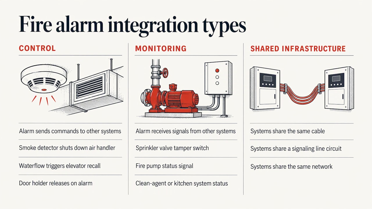
The word covers three different things, and mixing them up causes most of the confusion on projects.
Control interfaces. The fire alarm system sends a command to another system. A smoke detector in a return air duct shuts down an air handler. A waterflow switch triggers elevator recall. A door holder releases on alarm.
Monitoring interfaces. The fire alarm system receives a signal from another system. Examples are sprinkler valve tamper switches, fire pump status, and the status of a clean agent or kitchen suppression system.
Shared infrastructure. Two systems use the same cable, the same signaling line circuit, or the same network. This is where reliability questions get serious, because a failure in one system can reach the other.
A building can have all three. A warehouse might have valve supervision and fan shutdown (control and monitoring), plus a gateway that lets the facility’s building automation system display fire alarm status (information sharing). A data center might add a link to a clean agent release panel and to the security system.
Mandatory connections and optional connections
The adopted building and fire code decides which connections a building must have. We do not explain those triggers here. In one sentence: NFPA 72 governs how fire alarm interfaces are installed and tested, and the locally adopted International Building Code and International Fire Code, as amended by the state or city, decide which interfaces a given building needs. For how that plays out on projects, see our fire alarm guides and code questions.
What matters for this discussion is the difference in intent.
| Type of connection | Typical examples | Why it exists | Failure consequence |
|---|---|---|---|
| Life safety control | Smoke control fans and dampers, elevator recall, door release, HVAC shutdown | Changes how the building behaves during a fire | Direct effect on occupant safety |
| Fire protection monitoring | Sprinkler valve supervision, waterflow, fire pump status, suppression release | Tells responders and the owner the protection is in service | Loss of awareness of system status |
| Notification coordination | Voice evacuation, mass notification | Delivers the right message to the right people | Wrong or conflicting messages |
| Information sharing | Building automation display, security system status, industrial controls | Operational convenience and coordination | Loss of convenience, if isolated correctly |
The last row is the one that should never be able to harm the first three. That is the core design principle behind every safe integration.
The sequence of operation: where integration is really defined
A wiring diagram shows what is connected. It does not show what the building does in a fire. That is the job of the sequence of operation.
A sequence of operation describes, step by step, what happens when an initiating event occurs. It can be written as a narrative. On larger projects it is usually also written as an input/output matrix, also called a cause-and-effect matrix. Each row is an input, such as a duct detector, a waterflow switch, or a manual pull station on the third floor. Each column is an output, such as a fan shutdown, an elevator recall, a stairwell pressurization start, or a notification zone. A mark where they cross means “this input causes that output.”
The matrix earns its place for three reasons.
- It forces coordination. The mechanical engineer, the electrical engineer, the elevator contractor and the fire protection engineer all have to agree on one document. Conflicts show up on paper instead of in the field.
- It is what gets programmed. The panel programmer works from it. If the matrix is vague, the programming is a guess.
- It is what gets tested. A tester cannot witness behavior that was never written down.
The larger and more interconnected the building, the more the sequence matters. A small office with a few duct detectors can be described in a paragraph. A high-rise with stairwell pressurization, smoke exhaust, elevator control, voice evacuation and a central building automation system needs a full matrix with zones, delays and priorities.
Which system wins when they disagree
A fire alarm interface connects systems that may have conflicting goals. The building automation system wants to keep the space comfortable. The security system wants doors locked. The fire alarm system wants fans shut down, doors released and people moving.
The governing principle in NFPA 72 is that fire alarm functions take priority over non-fire-alarm functions. Mass notification is the notable exception: in an emergency that is not a fire, it may take priority. The practical consequence is that other systems should respond to the fire alarm system, and never the other way around. A security override that can hold a door locked during a fire alarm is a design defect, not a feature.
Isolating the fire alarm system from everything else
The most useful single document on this topic is a NIST study of fire alarm systems connected to other building networks. NIST identified the concerns that drive good design: preserving the integrity of the fire alarm system, isolating it from interference or failures in other building systems, meeting code and UL listing requirements, and controlling access to alarm functions.
In plain terms, four questions come up on every integration.
- If the other system fails, does the fire alarm still work? It must.
- If the other network is flooded with traffic or compromised, can that reach the fire alarm panel? It must not.
- Is the connecting equipment listed for the purpose? Listed means tested and certified by a recognized laboratory for a specific use.
- Who can change or silence alarm functions? Access should be limited and logged.
The tool that answers most of these is the gateway. NIST describes a gateway as a device that lets other systems obtain fire alarm information while protecting the fire alarm system from outside interference. It reads status from the fire alarm side and presents it on the other side, usually through a protocol such as BACnet or Modbus. The path is designed to carry information out, not commands in.
This is also why a gateway is not the same as plugging a panel into the facility’s general network. A listed gateway with traffic filtering is a controlled boundary. A shared Ethernet switch is not.
Same network or separate network
The trend in newer buildings is toward more connectivity: remote monitoring, cloud dashboards, analytics on detector data, and a single operator screen for everything. Those are real benefits for facility teams, and a well-designed fire alarm system can feed them.
The engineering question is how much of that to place on the fire alarm side of the boundary. Our position is simple. Where the goal is to see information, use a gateway or hard-wired input/output points. Where the goal is to control life safety equipment, use dedicated, listed, supervised connections. Reserve fully shared networks for cases where the project team has a clear reason and a clear plan for failure, access control and testing.
Smoke control: the interface with the least tolerance for error
Smoke control is the clearest example of why integration is not just a convenience. Fans, dampers, stairwell pressurization and exhaust all have to move in the right order, and the fire alarm system is usually the initiator. The sequence has to match what the smoke control engineer designed and what the mechanical contractor installed. If you manage a building with smoke control, our smoke control design and testing page describes what we do on these systems.

A related trend is the use of the building automation system as the controller for smoke control equipment. In that case the controls must be listed for smoke control service, which narrows product choices. That is a reason to settle the controls approach early, before mechanical submittals are released, and not at commissioning.
Integrated testing: proving the pieces work together
Each system is tested on its own under its own standard. The sprinkler system gets its tests. The fire alarm system gets its tests. The smoke control system gets its tests. None of those, alone, shows that the interfaces between them work.
That gap is what NFPA 4 addresses. It provides a framework for integrated fire protection and life safety system testing. A good integrated test plan is built from the same documents that define the integration:
- The list of systems and the people responsible for each
- The functional matrix, which is the cause-and-effect matrix
- Drawings showing where the devices are
- Test scenarios, each tied to rows in the matrix
- Scope, schedule and how often the testing repeats
The final report should record what was tested, how each system responded, which inputs and outputs were exercised, any faults found, and how they were corrected.
Two practical points follow. First, the quality of the integrated test depends on the quality of the matrix. Second, integration that was designed late tends to be tested badly. Teams that bring the test plan into the design phase find conflicts when they are cheap to fix.
What good integration documentation looks like
Plan reviewers see the same gaps again and again. A complete package for a project with interfaces typically includes:
- A written description of intent and how the system is supposed to behave
- A riser diagram showing panels, remote units and the pathways between them
- Equipment data sheets, including the listing for any gateway or interface module
- The sequence of operation, as narrative, matrix or both
- Manufacturer instructions for the interface devices
- A commissioning and testing plan
- Operations and maintenance manuals the owner can use ten years later
What the authority having jurisdiction (AHJ) will accept varies by city and fire district. Some local guidance restricts connections that others allow. For example, one fire district’s checklist generally bars connecting fire alarm systems to security or other non-fire systems, with a narrow exception for certain listed combination systems in single-tenant buildings. That is one jurisdiction’s rule, not a national one, which is why we confirm local practice before settling an integration approach.
Our perspective
Most integration problems we see are not equipment problems. They are coordination problems. The mechanical drawings show one sequence, the controls submittal shows another, and nobody has written down what the fire alarm panel is actually supposed to do.
We start with the sequence of operation and build the design around it. Every input and every output is written down, and each is traced to the discipline responsible for it. A licensed Professional Engineer stays on the project from first scope to final stamp, so the person who wrote the matrix is the person who answers when the reviewer asks about it.
We also write for the reviewer. Our designs are prepared with the local AHJ in mind in New York, New Jersey, Pennsylvania, Maryland and Delaware, because the same integration can be accepted in one jurisdiction and questioned in the next.
Our rule of thumb is to keep the fire alarm side simple and protected. Information can flow out freely through a gateway. Control of life safety equipment stays on dedicated, supervised connections. When the owner wants more, we design the boundary first.
DGA Fire Protection Engineering
Where we can help
If your project includes a fire alarm system that has to work with smoke control, sprinkler supervision, elevators, voice evacuation or a building automation system, we design the interfaces, write the sequence of operation and review the integrated test plan. Our fire alarm system design work is sealed by a licensed PE, and our engineers handle inquiries directly. You can see the full range of what we do on our services page.

For projects with voice evacuation or mass notification in the mix, we also cover that scope as part of the same coordinated design.
Questions to ask before you connect anything
Whether you are an owner, a contractor or a design professional, these questions catch most problems early.
- What is the connection for? Control, monitoring or information? The answer decides the equipment and the level of protection.
- What happens if the other system fails? The fire alarm system should be unaffected.
- Is the interface device listed for this use? Ask for the listing, not just a data sheet.
- Who owns the sequence of operation? One document, one owner, signed off by every discipline involved.
- How will it be tested? If nobody can describe the integrated test, the design is not finished.
- What does the AHJ expect? Local rules can add or restrict connections.
FAQ
What is the difference between fire alarm integration and interface?
People use the terms loosely. An interface is a specific connection, such as a signal to shut down an air handler. Integration is the overall result: how the fire alarm system and the other systems behave together. A building can have many interfaces and still be poorly integrated if the sequence of operation was never coordinated.
Can a fire alarm system share a network with building automation or security?
Sometimes, but the connection has to protect the fire alarm system. NIST highlights isolating the fire alarm system from failures and interference in other systems and controlling access to alarm functions, and gateways are the usual way to do that. Local rules can be stricter, and some jurisdictions generally prohibit connections to non-fire systems. Confirm with the AHJ early.
What is a cause-and-effect matrix?
It is a table that lists every input to the fire alarm system and every output it controls, and marks which inputs trigger which outputs. It documents the sequence of operation in a form that programmers, testers and reviewers can all use. On integrated projects it also becomes the basis for the NFPA 4 functional matrix.
Why do I need integrated testing if every system passed its own test?
Individual tests show that each system works. They do not show that the fan starts when the detector trips, or that the elevator recalls on the right signal. Integrated testing exercises the connections between systems under realistic scenarios and records the results.
Who should lead fire alarm integration on a project?
The fire protection engineer usually owns the fire alarm side and the sequence of operation, working with the mechanical, electrical and controls designers. Starting that coordination at schematic design is far easier than reconciling conflicting documents at commissioning. For how that relationship works, see our guide on working with a fire protection engineer.
If you have an integration question on a live project, talk to an engineer.
Sources
- NIST: Fire alarm systems with other building systems
- Sacramento Metropolitan Fire District: Installation of Fire Alarm Systems
Recommended
- Fire Alarm: Fire Protection Guides and Code Questions
- Fire Alarm Design Engineer NYC | NFPA 72
- Working with a Fire Protection Engineer: Fire Protection Guides and Code Questions
- FDNY Fire Alarm Letter of Approval & Plan Approval
Made with BabyLoveGrowth to reach more customers
This article is general information from DGA Fire Protection Engineering, not engineering advice for a specific building or project. Code requirements vary by jurisdiction and edition. Confirm with the authority having jurisdiction or a licensed fire protection engineer before acting on it.