
Fire pump testing
Diesel Fire Pump Acceptance Testing: An Owner’s Guide to NFPA 20
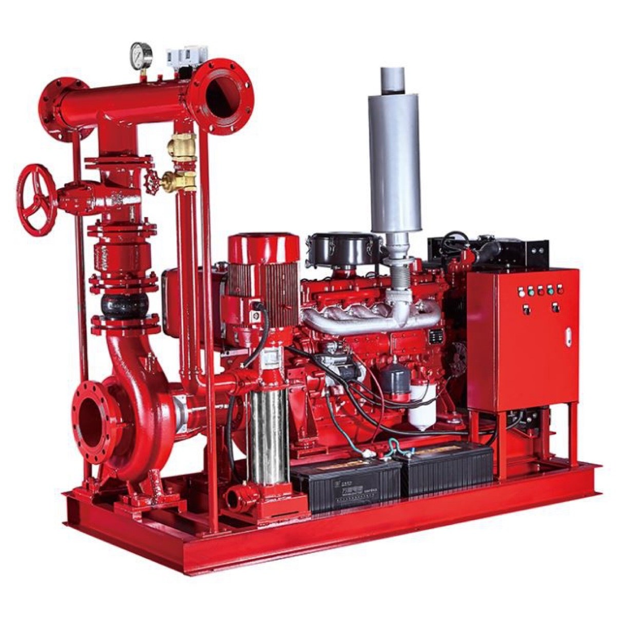
A diesel fire pump acceptance test is the field test that proves a new fire pump installation works before it goes into service. Under NFPA 20 (2022 edition), the pump, diesel engine, controller, and the installation around them are run under real flowing conditions and checked against the manufacturer’s certified test curve.
For building owners, it is the single most important quality checkpoint in a fire pump project. This guide walks through what happens before, during, and after the test, based on the acceptance checklist DGA Consulting uses in the field.
At a glance
- Governing standards: NFPA 20, Standard for the Installation of Stationary Pumps for Fire Protection (2022 edition), with NFPA 22 for suction tanks.
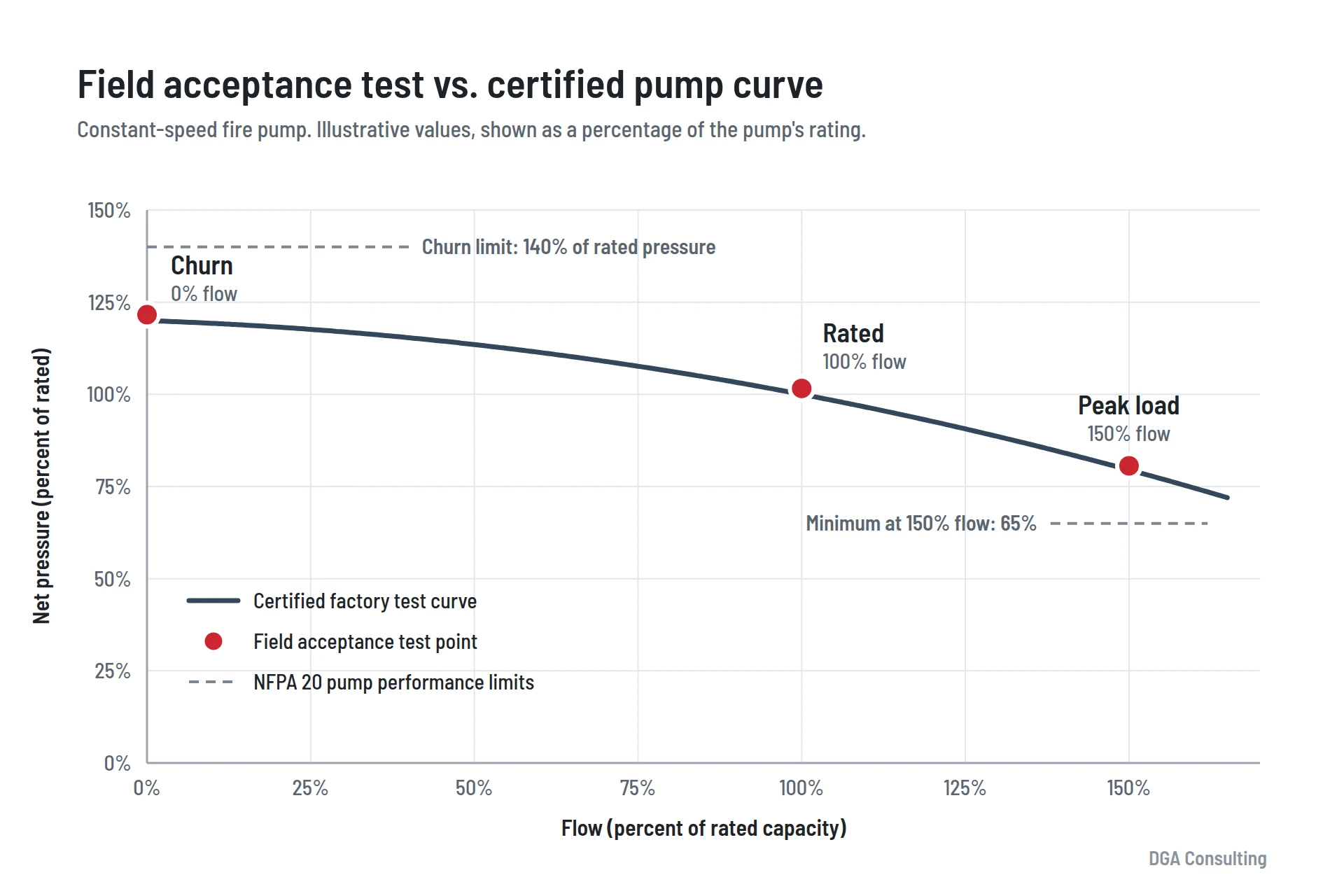
- Test points (constant-speed diesel pump): churn (no flow), 100 percent of rated flow, and peak load (generally 150 percent).
- Starting tests: a full-load start plus at least six automatic and six manual operations.
- Who attends: the pump and controller manufacturers or their factory-authorized representatives, typically with the installing contractor, the owner’s representative, and the authority having jurisdiction.
- Diesel-specific review: fuel tank sizing and piping, exhaust, starting batteries, ventilation, and the engine controller.
- What owners keep: the certified pump curve, field test results, gauge calibration records, the completed checklist, and a photo record.
In this guide
- What a fire pump acceptance test proves
- How to prepare for the test
- Required test points
- Post-test installation review
- Documentation owners should keep
- Frequently asked questions
What does a fire pump acceptance test prove?
Every fire pump is tested at the factory before it ships, and that test produces the certified pump test curve. The field acceptance test answers a different question: does the complete installation perform as designed, in place, under the conditions it will actually see?
During the test, water is flowed at several points across the pump’s range and the results are compared against the certified curve. Field results should meet or exceed the curve, or fall within the margin of error of the calibrated test gauges. If they do, the installation is sound. If they do not, something in the installation needs attention before anyone signs off.
How to prepare for a diesel fire pump acceptance test
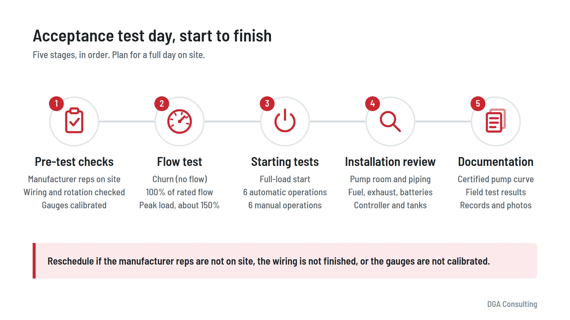
A smooth acceptance test starts well before water flows. Three things need to be in place: the right people, a finished installation, and the right equipment.
Who must be present
NFPA 20 requires the pump manufacturer and the controller manufacturer, or their factory-authorized representatives, to be present for the field acceptance test (§14.2.1). Their presence matters because installation problems are cheapest to fix while everyone with authority over the equipment is standing in the pump room.
Electrical work and pump rotation
All electrical wiring must be completed and checked by the electrical contractor before initial startup (§14.2.3). That includes wiring to any motors, control interwiring between multiple pumps, normal and alternate power supplies where provided, and the jockey pump. Pump rotation direction is verified at this stage as well.
Acceptance should never be granted on the assumption that an incomplete installation will be finished correctly later.
What to have on hand
- The manufacturer’s certified pump test curve, for comparison against field results (§14.2.4.1).
- Calibrated test equipment capable of measuring net pump pressure, flow rate, volts and amperes, and speed (§14.2.6.1.1). Ask for calibration documents for the suction, discharge, and pitot gauges, and flow coefficient data for the flow diffusers, playpipes, and nozzles.
- A camera. Photograph and video the entire pump room, plus every equipment placard: the fire pump, engine, controller, jockey pump and its motor and controller, and pressure relief valves. Take more photos than you think you need.
What is tested during a fire pump acceptance test?
The required flow test points depend on whether the pump runs at constant speed or uses variable-speed controls.
| Pump configuration | Required test points |
|---|---|
| Constant-speed | Churn (0% flow), rated flow (100%), and peak load (generally 150% of rated flow) |
| Variable-speed, in variable-speed mode | No flow, 25%, 50%, 75%, 100%, 125%, and 150% of rated load |
| Variable-speed, with variable-speed equipment disengaged | Minimum, rated, and peak loads at rated speed |
Peak load is the flow rate that requires the most horsepower, and it can occur below 150 percent of rated flow. A factory curve that shows horsepower draw identifies where it falls. For variable-speed pumps, the extra test points confirm that both the pump and the variable speed pressure limiting control (VSPLC) are operating correctly.
Diesel pumps with a pressure limiting driver (PLD)
Many diesel fire pumps use a pressure limiting driver, which slows the engine at low flows so discharge pressure stays below the system’s pressure rating, commonly 175 psi for sprinkler systems. As flow increases, the PLD brings the engine back up to rated speed. Where a PLD is installed, the review also confirms its 1/2 in. sensing line, which is typically connected between the discharge flange and the discharge check valve (§11.2.4.3.4).
Full-load start
The pump is brought from a standstill to rated speed without interruption while discharging at peak load (§14.2.6.11).
Six automatic and six manual starts
NFPA 20 calls for no fewer than six automatic and six manual operations during the acceptance test (§14.2.7.2), proving the starting systems work repeatedly, not just once. For diesel engines, a 5-minute run at full speed between successive starts is not required until cumulative cranking time reaches 45 seconds (§14.2.7.3).
Post-test installation review: what gets checked
Passing the flow test is necessary but not sufficient. The post-test review walks the installation against NFPA 20, and diesel drivers bring their own list. These are the items owners most often ask about.
Pump room
- Fire separation: indoor pump rooms need 2-hour separation without sprinklers or 1-hour separation with sprinklers. Outdoor pumps need 50 ft of clearance (§4.14.1.1.2).
- Sprinkler protection: designed per NFPA 13 as an Extra Hazard Group 2 occupancy (§4.14.1.3). DGA recommends high-temperature (286°F) sprinklers because of engine exhaust heat, although NFPA does not require them.
- Room conditions: heat, artificial lighting, battery-operated emergency lighting, ventilation, floors sloped to drains, and guards on shaft couplings (§4.14.3 through §4.14.7). Room temperature must stay at or above the engine manufacturer’s recommended minimum (§11.6.5).
- Ventilation: coordinated with the engine so it operates whenever the engine runs (§11.3.2.2). Motor-operated dampers should spring open and motor closed. In cold climates, keep water-filled piping out from in front of ventilation louvers.
Pressure gauges
The discharge gauge needs a 3.5 in. dial, a 1/4 in. gauge valve, and a range of at least twice the pump’s working pressure, but not less than 200 psi. The suction gauge is a 3.5 in. compound pressure and vacuum gauge with a range of twice the pump’s rated maximum suction pressure (§4.12).
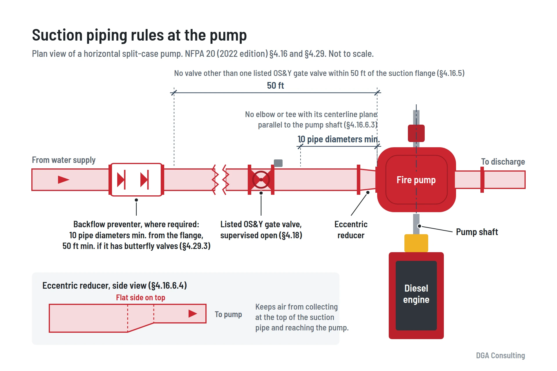
Suction piping
- A listed OS&Y gate valve in the suction pipe, with no other valve within 50 ft of the suction flange (§4.16.5).
- No elbows or tees with a centerline parallel to the pump shaft within 10 pipe diameters of the suction flange (§4.16.6.3).
- An eccentric reducer, properly oriented, wherever a reducer is needed on the suction side (§4.16.6.4).
- Backflow preventers at least 10 pipe diameters from the suction flange, or at least 50 ft if the assembly incorporates butterfly valves (§4.29.3).
- Suction and bypass piping sized per NFPA 20 Table 4.28(a).
- Strain relief where the pump and the suction supply sit on separate foundations (§4.16.6.5).
Discharge piping, test header, and valve supervision
- A listed check valve or backflow preventer in the discharge assembly, with a listed indicating gate or butterfly valve on the system side of the check valve (§4.17.7, §4.17.8).
- Suction, discharge, bypass, and backflow isolation valves supervised open. Test outlet valves supervised closed (§4.18).
- Where a flowmeter is installed, it must be capable of at least 175 percent of rated pump capacity (§4.22.2.2).
- Listed hose valves on the test header, sized per Table 4.28(a), with an automatic ball drip at the low point of the header supply line (§4.22.3).
- Hose header supply piping longer than 15 ft goes up one pipe size from Table 4.28(a), unless it is hydraulically calculated for 150 percent of rated capacity and proven by a full flow test (§4.22.3.4).
- Flowmeter piping kept within 100 ft of equivalent length, or the next larger meter size is required (§4.22.2.5, §4.22.2.6).
Jockey pump, relief valves, and pipe supports
- Jockey pump: steel pipe only for its suction and discharge lines (§4.27.6.1), with a check valve and an isolation valve in the discharge line (§4.27.6.3, §4.27.6.4). If its shutoff pressure exceeds the working pressure rating of the system, typically 175 psi, it needs a relief valve on its discharge (§4.27.5.1).
- Pressure relief valves, where provided: located between the pump and the discharge check valve (§4.20.3), discharging into an open pipe or cone so flow is visible (§4.20.5), with no shutoff valve in the supply or discharge piping (§4.20.9). If the discharge pipe has more than one elbow, it goes up one pipe size (§4.20.6.1.1).
- Pipe stands: stands under 4 ft tall can be 2 in. pipe. Each stand is anchored to the floor with at least two anchors, or four if it is over 4 ft tall (§4.15.6).
- Seismic bracing: per NFPA 13 where required, with a flexible coupling at the base of any riser that is part of the pump discharge (§4.30).
Pressure sensing line
The sensing line must be 1/2 in. nominal brass, copper, or stainless steel, with two ground-face unions at least 5 ft apart drilled with 3/32 in. orifices. Where the water is not clean, check valves with a 3/32 in. hole drilled in the clapper are required instead. No shutoff valves are permitted in the line (§4.32).
Diesel fuel system
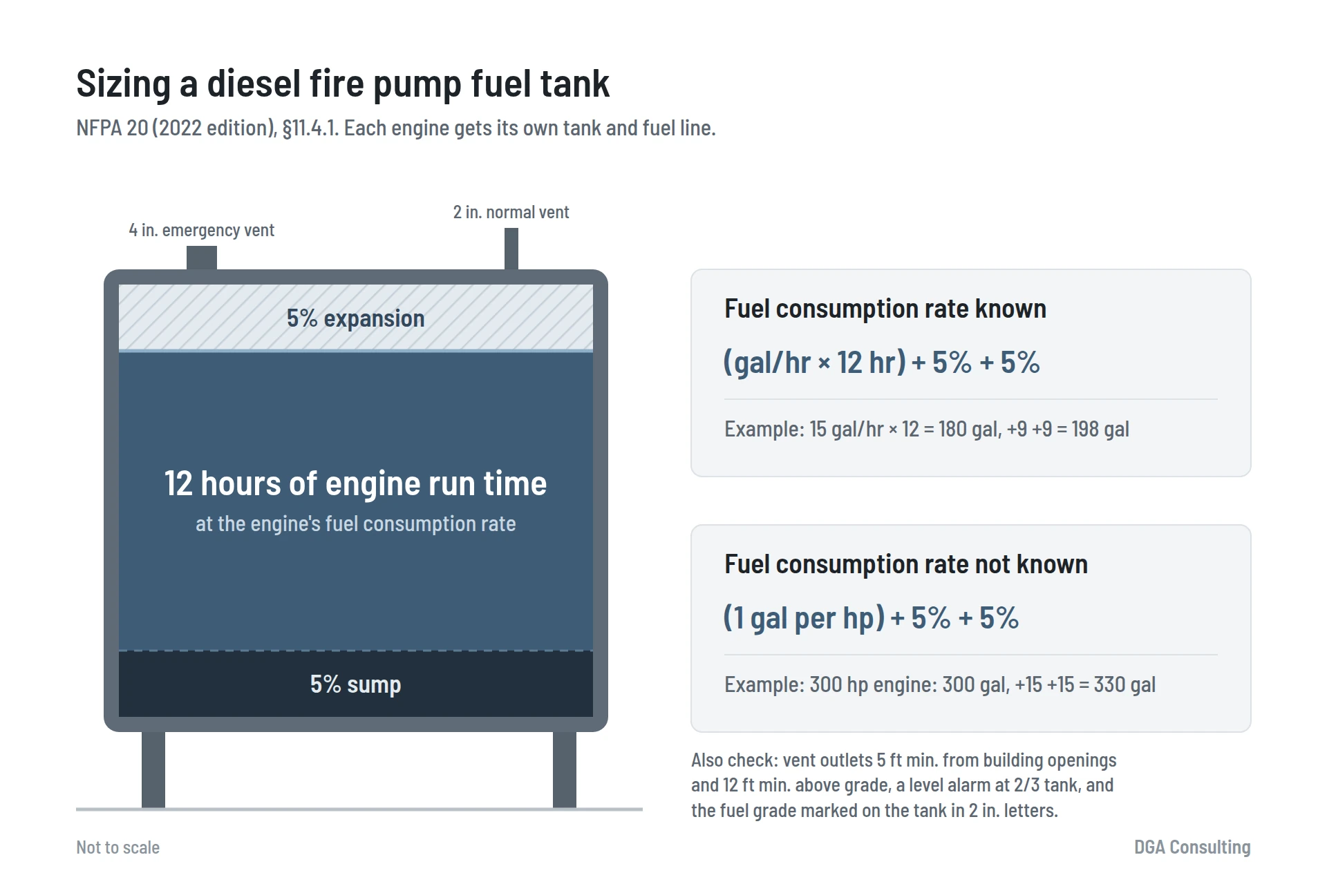
Each engine needs its own fuel tank and fuel line. Under NFPA 20 (2022), the tank must hold at least 12 hours of engine run time based on the engine’s fuel consumption rate, plus 5 percent volume for expansion and 5 percent for sump (§11.4.1.3.1). If the consumption rate is not known, the tank should hold at least 1 gallon per horsepower, plus the same 5 percent allowances (§11.4.1.3.1.1).
- Double-walled tanks: the space between the walls must be monitored for fuel leakage (§11.4.1.5.8).
- Vents: a 2 in. normal vent and a 4 in. emergency vent, with outlets at least 5 ft from building openings and at least 12 ft above finished grade (§11.4.1.6).
- Level indicator: activates at the two-thirds tank level (§11.4.2.2).
- Tank elevation: the fuel supply outlet can be no lower than the centerline of the engine’s fuel transfer pump (§11.4.3.3).
- Fuel piping: no galvanized steel or copper (black steel is preferred), listed flame-resistant flexible hoses at the engine, and guards on any line exposed to mechanical damage (§11.4.4).
- Valves: the fuel supply valve is locked open, and no other valve is allowed in the supply line. No shutoff valve is allowed in the return line (§11.4.4.4, §11.4.4.5).
- Labeling: the fuel grade is marked on the tank in 2 in. letters (§11.4.5.4).
Exhaust system
- An independent exhaust system for each engine (§11.5.2.1).
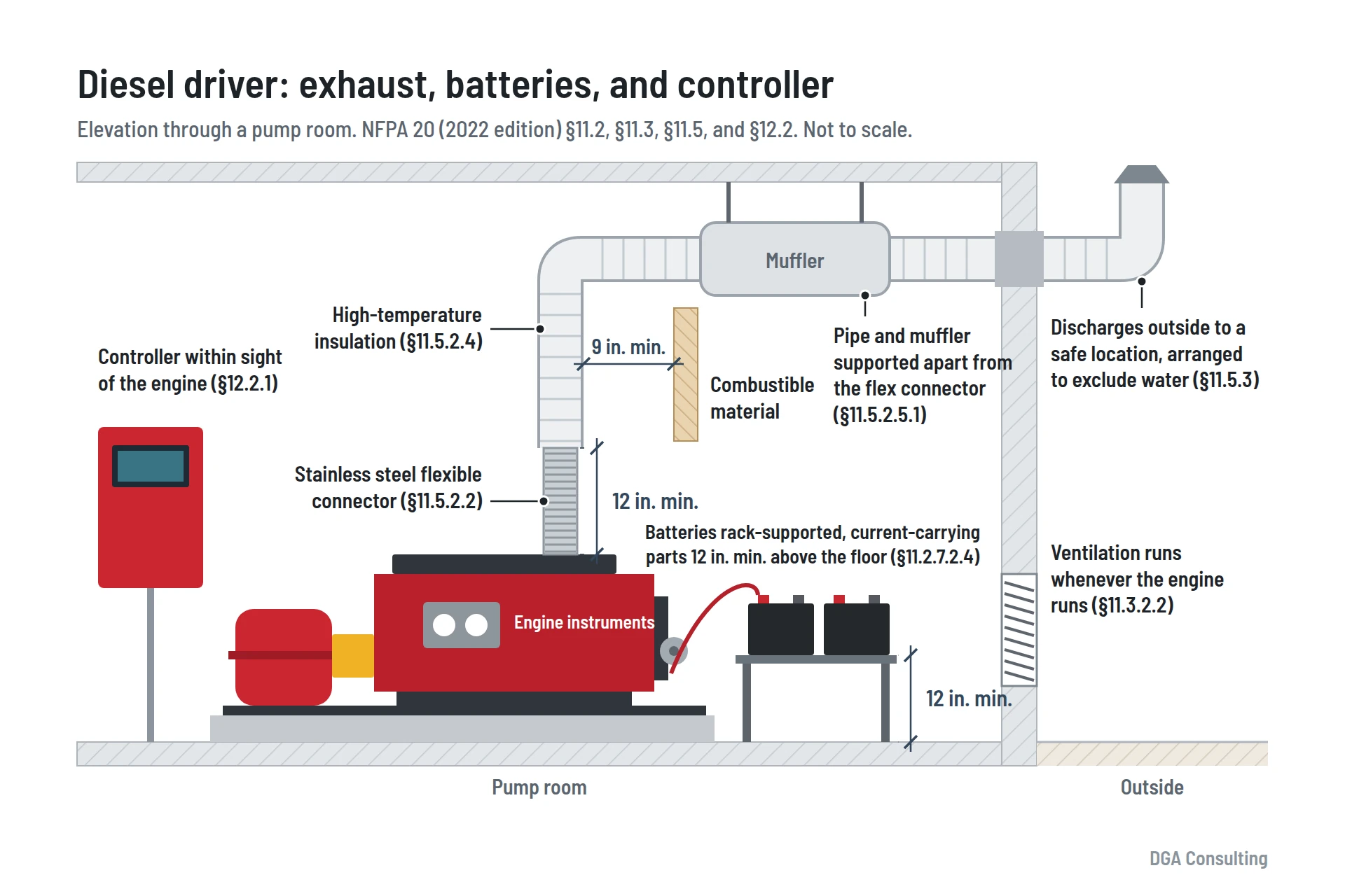
- A stainless steel corrugated flexible connector, at least 12 in. long, between the engine exhaust outlet and the exhaust pipe (§11.5.2.2).
- High-temperature insulation, with the exhaust pipe and muffler supported independently of the flexible connector (§11.5.2.4, §11.5.2.5.1).
- At least 9 in. of clearance to combustible materials (§11.5.2.6).
- Discharge to a safe location outside the pump room, arranged to exclude water (§11.5.3).
Starting batteries and engine controller
- Batteries rack-supported above the floor, secured against movement, with current-carrying parts at least 12 in. above the floor, and not located in front of the engine-mounted instruments and controls (§11.2.7.2.4).
- The controller located as close as practical to the engine and within sight of it (§12.2.1), in a minimum NEMA Type 2 drip-proof enclosure (§12.3.3.1.1).
- Neither the controller enclosure nor the engine control panel used as a junction box for other equipment or AC supply (§12.3.5.3.1, §11.2.5.1.2).
- Where the pump supplies deluge or dry pipe valves, the controller starts the engine when that equipment activates (§12.7.2.2).
- Where multiple pumps are installed, controllers start them in sequence at 5 to 10 second intervals (§12.7.2.5.3).
Suction tanks, where provided
Where a suction tank supplies the pump, NFPA 22 and related standards add their own checks:
- Heaters where the design requires them for cold weather, with a thermometer, plus a low water temperature supervisory switch.
- Water level supervisory switches.
- Fill valve supervision: the manual fill valve and automatic fill bypass supervised closed, automatic fill isolation valves supervised open, and the automatic fill solenoid controlled by a fire alarm control module.
- Confined-space entry signage at each manway.
- Grounding lugs connected to a grounding rod, and finished grade at least 6 in. below the top of the ring wall foundation.
Fire pump acceptance test documentation owners should keep
When the test is done, the owner should walk away with:
- The manufacturer’s certified pump test curve
- The field test results
- Gauge calibration records and flow coefficient data
- The completed acceptance checklist
- The photo and video record
Together, these form the baseline that every future annual fire pump test under NFPA 25 will be measured against.
Key takeaway: never accept a fire pump installation on promises. The acceptance test exists so that every claim about the installation is verified with water flowing and instruments reading. If the manufacturer’s representatives are not in the room, the wiring is not finished, or the gauges are not calibrated, reschedule.
Fire pump acceptance test witnessing in New York, New Jersey, and Pennsylvania
DGA Consulting’s fire protection engineers witness and document fire pump acceptance tests, review installations against NFPA 20, and help owners resolve deficiencies before final acceptance. The firm’s engineering is led by a Professional Engineer licensed in New York, New Jersey, and Pennsylvania, and DGA Consulting works with diesel and electric fire pumps across commercial, industrial, and institutional facilities.
Frequently asked questions
When is a fire pump acceptance test required?
After a new fire pump is installed and before it is placed in service. The field acceptance test is required by NFPA 20 and is typically witnessed by the authority having jurisdiction.
Who needs to be present at a fire pump acceptance test?
At minimum, the pump and controller manufacturers or their factory-authorized representatives, the installing contractor, and the owner’s representative. The authority having jurisdiction is often present as well.
What is a churn test on a fire pump?
Churn is the pump running at zero flow with the discharge shut. It establishes the maximum pressure the pump can develop and is one of the three standard test points for constant-speed pumps.
How big does a diesel fire pump fuel tank need to be?
Under NFPA 20 (2022 edition), the tank must hold at least 12 hours of engine run time based on the engine’s fuel consumption rate, plus 5 percent for expansion and 5 percent for sump. If the consumption rate is not known, the tank should hold at least 1 gallon per horsepower plus the same allowances. Each engine needs its own tank.
How long does a fire pump acceptance test take?
It depends on the complexity of the installation, but owners should plan for a full day, including setup, the flow test, the starting tests, and the installation review.
What happens if a fire pump fails the acceptance test?
Deficiencies are documented and corrected, and the affected portions of the test are repeated. Acceptance is granted only when the installation demonstrates compliance.
How is an acceptance test different from annual fire pump testing?
The acceptance test under NFPA 20 happens once, before the pump is placed in service. After that, NFPA 25 governs ongoing inspection, testing, and maintenance, including an annual flow test whose results are compared against the acceptance test baseline.
Have a fire pump acceptance test coming up in New York, New Jersey, or Pennsylvania? Contact DGA Consulting for a plain-English answer.